| |
-
V-Caps use solid-core copper leads (18 AWG or 21 AWG). Because of the nature of solid core copper, extra care should be exercised when bending the leads for installation. A gentle radius bend is better than an acute bend.
-
Leads should be kept as short as possible, and the caps should be mounted securely. 3M double-sided foam tape works well, as does nylon ties for the heavier parts. If using nylon ties on TFTF or CuTF series parts, secure at the OUTER EDGES (not central portion), and avoid over-tightening. Damage may occur, if excess pressure is placed on the capacitor body. If using nylon ties, ensure the square receptacle end does not make contact with the capacitor body. The corners may pierce the outer dielectric if allowed to make contact, and cinched tightly. Silicone tape may also be used as a 'pad' to physically/electrically buffer the capacitor body from surrounding components.
-
Exercise care when soldering, using soldering best practices.
Use a heatsink with OIMP, ODAM or TONE capacitor leads. A copper alligator clip between the solder connection and the point where the lead enters the cap body works well.
Don't apply heat to the solder connection for a lengthy period of time. This may result in excessive heat buildup, and compromise the electrical connection of the lead to the cap winding, or compromise the hermetic seal. Try to maintain AT LEAST 1/2" distance from the solder installation point from the 'bead' of solder that secures the electrical lead material to the hermetic seal. Excess heat can cause seal failure and leakage of the fluid!
-
Although the V-Caps are not polarized, many have found it best to keep the lead orientation relative to the innermost and outermost foil consistent between left and right channels. Placement of the outer foil for each V-Cap series is listed below. Note that these are general guidelines, and there may be instances where reversing the caps may prove to be preferred in your system
-
Do NOT use across AC line. V-Caps are not rated for use across AC line, which require special 'X' or 'Y' rated caps that meet certain failure criteria. Using across AC line voltage is at buyer's risk.
-
Do NOT use in a circuit that has DC voltage spikes that exceed the DC rating of the V-Cap.
CuTF & TFTF Series |
ODAM, TONE & OIMP Series |
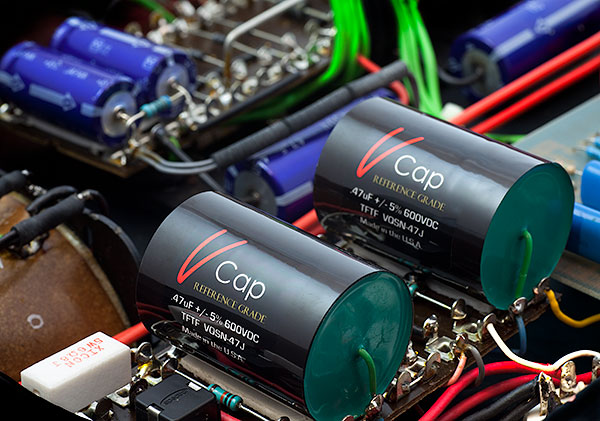
- The green lead indicates the outermost foil, and should be connected to the lowest impedance path to ground. Another way to identify outer foil is the writing on the label flows towards the outer foil.
- Use a quality wire stripper when removing the insulation, like a Klein No. 11055
- When used in amplifiers, outer foil should be connected towards the plate of first stage
- If using as a bypass cap to ground, connect green lead to ground.
- If using as a bypass cap from a signal to B+, connect green lead to B+.
- If using in a feedback position, connect green lead towards the output
- When securing near objects or circuit traces that have sharp edges, Silicone tape can work well as a buffer, to prevent laceration of the V-Cap's outer skin.
|
- The short lead indicates the outermost foil, and should be connected to the lowest impedance path to ground. Another way to identify outer foil is the writing on the label flows towards the outer foil.
- The ODAM, TONE, and OIMP series capacitors have metal bodies that are electrically conductive. Ensure that the body doesn't make electrical contact with any other portion of the circuit other components or electrically LIVE circuit traces. Heatshrink, 3M foam tape, or silicone tape around the body may be used to help insulate, and protect from electrical short. The TONE Cap series with values from .01 uF to .047 uF have a clear insulating sleeve over the brass canister and provides some isolation, but you should still safeguard against any laceration or puncture of this 'skin' to prevent any short...
|
< Back to Tech Room
|
|